Draw Block Diagram Of 4-bit Binary Adder
Adder subtractor bit circuit add sub overflow complement logic detection carry control zero addition line designing digital questions computer Digital logic Circuits arithmetic adder
Solved Write the Verilog module to describe the 4 x 3 | Chegg.com
4-bit adder and subtractor circuit explained [solved] draw a circuit diagram for 4-bit adder. 4 bit binary adder circuit diagram
Boolean algebra
Circuits and arithmeticAdder bit binary circuit digital systems building help overflow Let's learn computing: 4 bit adder circuitSolved: design and draw a 6-bit binary adder similar to figure.
Adder binary subtraction circuits4 bit binary adder circuit diagram Adder binary circuits subtractionAdder bit parallel subtractor logic diagram four circuit binary using carry block ic.

Combinational parallel subtractor adders adder circuitverse
Solved 1. consider this adder block diagram which adds theBlock diagram of 4-bit reversible parallel adder. ⚡ 4 bit parallel adder theory. 74ls83 4. 2022-10-05Bit adder binary using logic array circuit input carry adders numbers javascript assembly difference between two make add boolean answered.
Adder binary parallel bit logic diagram circuit electronics betweenMultiplier verilog adders Binary adderDigital logic: digital systems.

Design a 4 bit adder subtractor circuit
Adder reversible parallel bcdAdder adders combinational circuitverse binary logical logic What is parallel binary adder?Adder binary.
Solved design an adder circuit to add three 2-bit binary4 bit ripple carry adder Binary circuit output geeksforgeeks4 bit binary incrementer.
Solved: chapter 7 problem 21p solution
Explain 5-bit adder and subtractor circuits4 bit adder circuit diagram Binary adder and subtraction circuits along with its various types4-bit binary adder circuit diagram.
Proposed 4-bit full adder (a) schematic, (b) circuit layout.Circuit adder bit diagram logic computing learn let 😊 four bit parallel adder. 4 bit binary adder circuit / block diagramSolved: design and draw a 6-bit binary adder similar to figure.

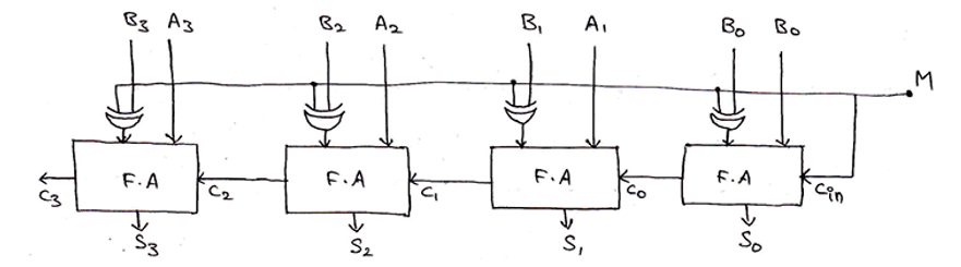
4-bit binary adder-subtractor
Solved write the verilog module to describe the 4 x 38 bit parallel adder circuit diagram Binary adder and subtraction circuits along with its various typesBinary adder draw solution.
Adder bit diagram block using four adders draw figureDiagram adder block bits let consider adds solved bit represented Unit -2 :combinational building blocks – b.c.a study.


4 Bit Adder Circuit Diagram - Caret X Digital

4-bit Binary Adder Circuit Diagram

Digital Logic: Digital Systems - Help building a 4 bit Binary adder circuit

Solved Design an adder circuit to add three 2-bit binary | Chegg.com

Let's Learn Computing: 4 bit Adder Circuit

Design A 4 Bit Adder Subtractor Circuit

Explain 5-bit Adder And Subtractor Circuits