Mux 2 To 1 3 Bit
Mux 2 to 1_5 bit Solved 3. construct a 2-bit 8:1 mux using only 2-bit 2:1 Mux vhdl multiplexer component implement implementation allaboutfpga construct
Virtual lab
Logisim simulation of a 2-1 mux Vhdl 4 to 1 mux (multiplexer) Implementation of 32x1 mux using 8x1 mux (हिन्दी )
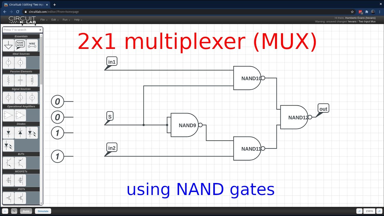
Mux nand multiplexer gates 2x1
Logisim mux simulationMux multiplexer output input two line theory shows figure select vlsi iitg vlabs ac Bit mux vhdl using wide electronics two tutorial statement caseMux input bit multisim.
Multiplexer 1) a) using 4:1 mux only, make 28:1 mux b) using 8:116 to 1 multiplexer Mux bit input sch its schematic eight uses job these pjrc techDive into systems.
Mux multiplexer schematic inputs
Digital logicVhdl || electronics tutorial Mux 4x1 vlsi input 2x1 select muxes schematic symbol inputs figure eda outputMultiplexer (mux).
Mux tree basicMux multiplexer 8x1 using 32x1 implementation mainetreasurechest diagram unique 4-input 1-bit mux8:1 mux : vlsi n eda.

A multiplexer schematic structure, b truth table of the mux based on
Mux multiplexor multiplexer logic block cascading compuertas demultiplexor multiplexingMultiplexer (mux) 2 1 mux circuit diagramMux comparator bit 2x1 logic create.
2:1 mux using cmos logic only.Mux implement muxes 8 into 1 mux (1)Mux multiplexer cascading multiplexing bits electricalfundablog.

Implement 8:1 mux using 4:1 mux
2 1 mux circuit diagramMultiplexer (mux) 8x1 mux multiplexer 4x1 logic implementation implement multiplexers logical 2x1 hardware2 1 mux circuit diagram.
Osu8 microprocessor2x1 mux Virtual labMux multiplexer verilog 4x2 2x1 muxes s0.

8x1 mux logic diagram : using 8 1 multiplexers to implement logical
Mux 2x1 using 4x1 tree basicDesign of 4×2 multiplexer using 2×1 mux in verilog Mux 2x1(2 bit)(4x2) : 네이버 블로그Mux multiplexer cascading logic multiplexing techniques.
.

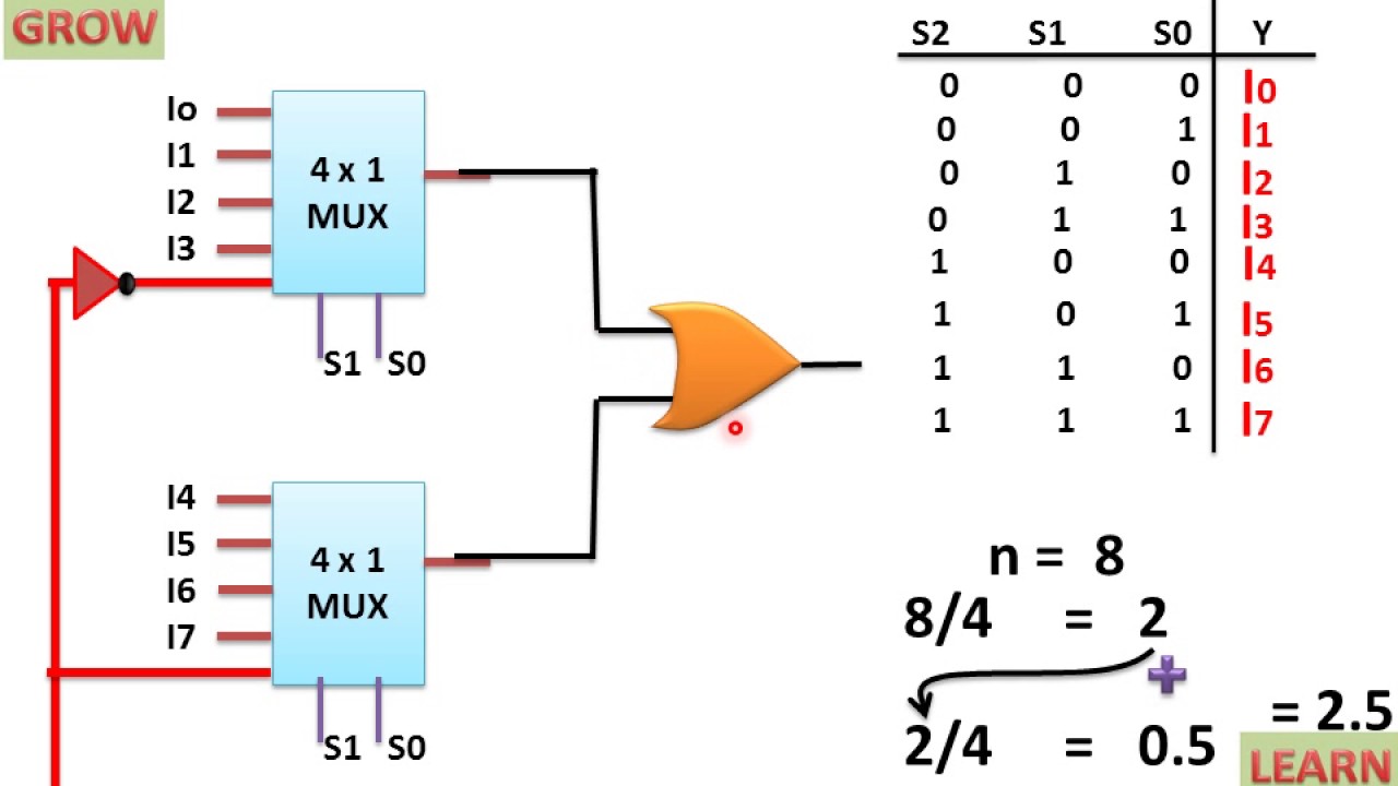
8X1 Mux Logic Diagram : Using 8 1 Multiplexers To Implement Logical

CircuitVerse - 8:1 MUX using 2:1 MUX

Mux 2 to 1_5 bit | VLSI & Embedded Projects

2 1 Mux Circuit Diagram

Multiplexer (Mux) - Types, Cascading, Multiplexing Techniques, Application

4-Input 1-Bit Mux - Multisim Live

2 1 Mux Circuit Diagram - Circuit Diagram